Motors and Controllers
Motors are devices that convert electrical energy into mechanical energy, or vice versa for generators. There are two main types of motors: AC and DC powered motors. AC motors operate on alternating current, which changes its direction and magnitude periodically, while DC motors operate on direct current, which has a constant direction and magnitude.

DC motors are widely used in various applications that require precise control, high torque, or variable speed. There are different types of DC motors, such as geared motors, stepper motors, and servos.


Geared motors are DC motors that have a gearbox attached to them, which reduces the speed and increases the torque of the output shaft. Geared motors are suitable for applications that require high torque at low speed, such as conveyor belts, elevators, or robots.

Stepper motors are DC motors that rotate in discrete steps, which can be controlled by pulses of current. Stepper motors are ideal for applications that require accurate positioning, such as printers, scanners, or CNC machines.
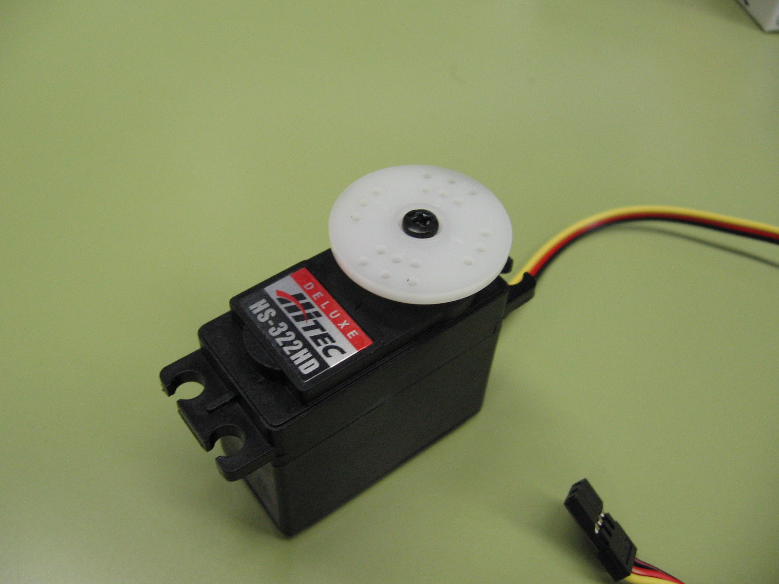
Servos are DC motors that have a feedback mechanism that allows them to adjust their position and speed according to a signal from a controller. Servos are commonly used for applications that require precise angular movement, such as robotic arms, cameras, or antennas.
When selecting a motor for a mechanical design, there are several factors to consider, such as the required speed, torque, power, efficiency, size, shape, cost, and reliability. Depending on the application and the specifications, different types of motors may be more suitable than others. Therefore, it is important to understand the principles of motor selection and compare the advantages and disadvantages of each motor option.
- AC Motors – Large applications, high efficiency, precise control of continuous rotational speed.
- DC Geared Motors – Smaller sizes, within product or system, precise control of continuous rotation
- Stepper Motors – High torque holding capacity, precise control of rotation angle or rotational position.
- Servo Motors – Inexpensive limited rotational motion, precise control of limited range of motion (commonly 180 degrees).
How Do Motors Even Work?
Motor Specification
DC Geared Motors
The speed and torque of a DC motor are determined by its voltage, current, resistance, and armature constant. The armature constant for a dc motor is a parameter that relates the torque produced by the motor to the current flowing through the armature. The armature constant is also known as the torque constant or the motor constant. The armature constant can be calculated by dividing the torque by the current, or by multiplying the back emf constant by the motor efficiency. The armature constant depends on the design and construction of the motor, such as the number of turns, the length and cross-sectional area of the wire, and the magnetic flux density.
The following formula can be used to calculate the speed and torque of a DC motor:
Speed (in rpm) = (Voltage – Current * Resistance) / Armature constant
Torque (in Nm) = Current * Armature constant
To select a DC motor, we need to know the desired speed and torque of the system, as well as the available voltage and resistance. Then, we can use the formula to find the current and armature constant of the motor. Alternatively, we can look up the specifications of different motors and compare them with our requirements.
A supplier or manufacturer can provide you with the specific speed/torque curves for a particular motor. See the guide from ISL here: How To Read DC Motor & Gear Motor Performance Curves | ISL Products
For example, suppose we want to design a system that needs a speed of 3000 rpm and a torque of 0.5 Nm. We have a voltage source of 12 V and a resistance of 1 ohm. Using the formula, we can find that the current and armature constant of the motor should be:
Current = (Voltage – Speed * Armature constant) / Resistance
Armature constant = (Voltage – Current * Resistance) / Speed
Plugging in the values, we get:
Current = (12 – 3000 * Armature constant) / 1
Armature constant = (12 – Current * 1) / 3000
Solving for Current and Armature constant, we get:
Current = 0.004 A
Armature constant = 0.004 Nm/A
Therefore, we need to select a DC motor that has a current rating of 0.004 A and an armature constant of 0.004 Nm/A. We can search for such a motor online or in a catalog and check its other features, such as size, weight, efficiency, etc.
Stepper Motors
A stepper motor is a type of electric motor that can rotate in discrete steps, which makes it suitable for precise positioning and speed control. To select a stepper motor for a machine application, you need to consider the following factors:
- The torque and speed requirements of the load. The torque is the force that the motor can exert on the load, and the speed is the number of revolutions per minute (RPM) that the motor can achieve. The torque and speed are inversely proportional, meaning that as one increases, the other decreases. Therefore, one needs to find a balance between the two that meets the performance criteria of the application.
- The power supply and driver circuit of the motor. The power supply provides the voltage and current that the motor needs to operate, and the driver circuit controls the switching of the coils inside the motor to create the desired motion. The power supply and driver circuit should match the specifications of the motor, such as the rated voltage, current, phase, and step angle.
- The size and mounting of the motor. The size of the motor determines how much space it occupies in the machine, and the mounting refers to how the motor is attached to the load or the frame. The size and mounting should be compatible with the design and layout of the machine, as well as the environmental conditions, such as temperature, humidity, and vibration.
Supplier websites will help you find the appropriate stepper motor for you application. For example, see: Selection Guide for Stepper Motors | Motion Control Products
Servos
To select a servo motor for an application, the primary selection factors are: the required torque, speed, accuracy, and feedback. The torque is the rotational force that the motor can produce, and it depends on the load and the inertia of the system. The speed is the rotational velocity that the motor can achieve, and it is related to the voltage and the frequency of the power supply. The accuracy is the degree to which the motor can match the desired position or velocity, and it is influenced by the resolution and the linearity of the feedback device. The feedback device is a sensor that measures the actual position or velocity of the motor and sends it back to the controller, which adjusts the output accordingly. A common feedback device is an encoder, which can be incremental or absolute. An incremental encoder counts the pulses generated by the motor rotation, while an absolute encoder provides a unique code for each position.
Servo motors can be selected from small hobby size to significant holding torques for industrial applications. See an example supplier here: Shop Industrial Servo Motors – MRO Electric and Supply
Linear Actuation
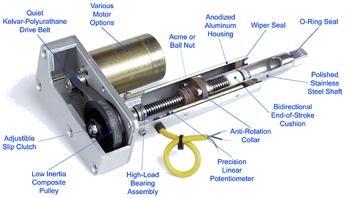
An electrical linear actuator is a device that converts the rotational motion of an electric motor into linear motion, allowing it to move objects in a straight line. Electrical linear actuators typically consist of an electric motor and a screw mechanism, such as a lead screw, a ball screw, or a roller screw, that translates the rotary motion of the motor into linear displacement. Electrical linear actuators are widely used in various applications, such as industrial machinery, medical equipment, robotics, and automation systems.
To select an electrical linear actuator for a machine, the controlling factors are: the required force, speed, stroke length, accuracy, repeatability, duty cycle, environmental conditions, and control options.
- The force of an electrical linear actuator is determined by the torque of the motor and the pitch of the screw.
- The speed of an electrical linear actuator is inversely proportional to the force.
- The stroke length of an electrical linear actuator is the maximum distance that the actuator can travel.
- The accuracy and repeatability of an electrical linear actuator depend on the precision and backlash of the screw mechanism.
- The duty cycle of an electrical linear actuator is the percentage of time that the actuator can operate without overheating.
- The environmental conditions of an electrical linear actuator include the temperature, humidity, dust, vibration, and corrosion resistance.
- The control options of an electrical linear actuator include the type of motor (AC or DC), the feedback device (encoder or potentiometer), and the communication protocol (analog or digital).
Electrical linear actuators offer many advantages over other types of actuators, such as hydraulic or pneumatic actuators. They are more energy-efficient, precise, reliable, quiet, clean, and easy to install and maintain. However, they also have some limitations, such as lower force capacity, higher cost, and higher complexity. Therefore, one should carefully evaluate the needs and specifications of the machine before choosing an electrical linear actuator.
Hydraulic or pneumatic linear actuators use pressurized fluid (air or liquid) to drive a piston and achieve linear motion. These actuators can be more powerful and cheaper but come with the added complication of the supporting hydraulic or pneumatic pressure system. Some examples of where pneumatic or hydraulic linear actuators are used are:
- Valves: Pneumatic or hydraulic actuators can control the opening and closing of valves in pipelines, pumps, tanks, etc. They can provide fast and accurate valve positioning, as well as high torque and pressure resistance.
- Robotics: Pneumatic or hydraulic actuators can provide smooth and flexible movement for robotic arms, grippers, joints, etc. They can also offer high load capacity, speed, and durability.
- Automotive: Pneumatic or hydraulic actuators can operate various components in vehicles, such as brakes, clutches, steering, suspension, etc. They can ensure reliable and safe performance, as well as energy efficiency and noise reduction.
Motor Control
Motor control boards or control drivers are used to regulate the operation of motors. These devices are separate from the control logic boards that provide the instructions for the motor, because high power motors require high power supplies which would be too much for sensitive logic control boards. Motor control is usually accomplished with a packaged motor control board and software solution.
