Motion and Control of Mechanisms
Degrees of Freedom and Mobility
Joints
Mechanisms and other kinematic chains are made of linkages that are connected together at joints. The type of joint defines how the bodies are allowed to move with respect to each other. A free-floating object in space has six degrees of freedom (DOF), meaning that it can translate in three directions and rotate about three arbitrary orthogonal axes. When bodies or links are joined together, they impose restrictions on the motions that are allowed, reducing the DOF of the entire object.
Joints are described based on the DOF they allow. There are six types of joints called lower pairs:
- Revolute joint: Allows one DOF, rotation.
- Prismatic joint: Allows one DOF, translation.
- Screw or helical joint: Allows one DOF, a combination of rotation and translation.
- Cylindrical joint: Allows two DOF, rotation and translation along a common axis.
- Spherical joint: Allows three DOF, rotation about three orthogonal axes.
- Flat surface joint: Allows two translations and one rotation.
Common higher-order pairs involve objects with rolling contact, such as gear teeth meshing, cam and follower action, and other rolling elements. There is an unlimited number of possible higher-order pairs, and thus no standard classification for them.
Planar and Spatial Motion
Planar and spatial mechanisms are two broad categories of mechanisms that are distinguished by the dimensionality of their motion. Planar mechanisms are constrained to move in a single plane or in parallel planes, while spatial mechanisms can move in three dimensions.
Planar Mechanisms
Planar mechanisms are very common in engineering applications, and they can be used to create a wide variety of machines and devices. Planar mechanisms are often simpler to design and analyze than spatial mechanisms, and they can be more efficient and reliable in operation. All motion in planar mechanisms is restricted to two translation directions and one rotation direction. This means that planar mechanisms can be readily synthesized and analyzed using graphical or computational methods in a plane (such as by hand on a piece of paper).
Spatial Mechanisms
Spatial mechanisms are more complex than planar mechanisms, but they offer greater flexibility and versatility. Spatial mechanisms are often used in applications where three-dimensional motion is required, such as robotics, aerospace engineering, and machine tools.
| Characteristic | Planar Mechanism | Spatial Mechanism |
|---|---|---|
| Dimensionality of motion | Constrained to a single plane or in parallel planes | Free to move in three dimensions |
| Complexity | Simpler to design and analyze | More complex to design and analyze |
| Efficiency and reliability | More efficient and reliable | Less efficient and reliable |
| Versatility | Less versatile | More versatile |
While planar mechanisms are constrained to move in a single plane or in parallel planes, there are ways to use them to achieve three-dimensional motion. For example, scissor lifts use two planar four-bar linkages in parallel planes to create a stable lifting platform. Another example is a parallel manipulator, which uses four planar four-bar linkages to create a six-DOF robot arm.
Mobility
The mobility of a linkage mechanism is the number of independent inputs required to define the configuration of all the links. In other words, it is the number of degrees of freedom of the mechanism. The mobility of a linkage mechanism can be determined using the Chebychev–Grübler–Kutzbach equation, which is given by:
[latex]M = 3\left(L - 1\right) - 2J - H[/latex]
where:
- M is the mobility of the mechanism
- L is the number of links in the mechanism
- J is the number of joints in the mechanism
- H is the number of higher-order pairs in the mechanism
Higher-order pairs are joints that allow more than one degree of freedom, such as gear teeth meshing and cam and follower action.
Example
Consider a simple four-bar linkage, which has four links and four revolute joints. The Chebychev–Grübler–Kutzbach equation for this mechanism is:
M = 3(4 - 1) - 2(4) - 0 = 1
Therefore, the mobility of the four-bar linkage is one, meaning that it has one degree of freedom.
Why does the mobility of a mechanism matter to the machine designer? Because the DOF of the mechanisms is exactly the same as the number of independent drivers needed to control the motion. Can I achieve the motion I want with only 1 motor? Yes, if and only if the degrees of freedom of the machine using the mobility equation is equal to 1.
What if you apply the above mobility equation and come up with a number that you do not want? A mobility of zero means you have designed a structure. A mobility greater than 1 may be acceptable. You can utilize additional controlled actuation like motors or add some forcing element such as a spring. This latter approach is often used to ensure that a follower stays in contact with a cam as the otherwise the DOF would be greater than 1.
By studying the mobility equation, the designer can see that there are some principles that can be used to achieve a desired mobility. These principles are:
- You can replace joint types without affecting the mobility of the mechanism as long as the joints have the same DOF. For example, you can replace a revolute joint with a prismatic joint to go from a rocking motion to a sliding motion and still drive the machine with one actuator. However, for a planar mechanism, there must be at least 2 revolute joints in order for the mechanism to move at all.
- If you replace lower pair with a higher order pair you will increase the total DOF by 1. For example, replacing a pin in a hole (revolute) with a pin in a slot moves from just rotation to rotation and translation.
- Removing a link result in decreasing the mobility by 1 DOF. Thus, if you change a joint to a higher order and remove a link this results in mechanism with the same mobility.
- If you decrease the number of nodes on a link that has 3 or more nodes by having 1 node connect 2 or more links together, there is no change to the mobility. This means that a link shape can be changed to combine links to join together at the same location. Note, this will change the resulting motion of the machine.
- If you take the step above to the extreme and combine all links together at 1 joint, you have effectively eliminated a link and the result is a decrease in mobility by 1 DOF.
Grashoff and Mechanism Actuators
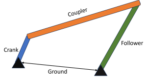
Four-bar linkages are one of the most common types of linkage mechanisms. They are composed of three links (crank, coupler, and follower) and a ground link (the distance between ground points). The link names are shown in the figure below.
Open the following and try changing the link lengths. You can drag any of the end points of the links and see how it moves.
- Find a combination of link lengths where one of the links draws a full circle. Then change the link lengths so that none of the links show complete circles (only arcs).
- What do you notice about the mechanisms that fully rotate and ones that don't?
https://www.geogebra.org/classic/BueCG9ch
Many linkage mechanisms are used for consistent, reliable, and repeated actions at a constant rate. One way to achieve this is to drive or actuate the mechanism with something that is consistent and reliable such as a motor operating a constant speed.
The Grashof criterion is a mathematical test that can be used to determine whether a four-bar linkage can achieve continuous rotation. It is named after its inventor, Franz Grashof, a German engineer who lived in the 19th century.
The Grashof criterion states that for a four-bar linkage to be capable of continuous rotation, the sum of the shortest and longest link lengths must be less than or equal to the sum of the remaining two link lengths. In mathematical terms, this can be expressed as follows:
S + L ≤ P + Q
where:
- S is the shortest link length
- L is the longest link length
- P is the medium link length
- Q is the remaining link length (it doesn't matter which is which for P and Q)
If the Grashof criterion is not satisfied, then none of the links can fully rotate. From a practical control standpoint, that means you cannot easily drive the motion using a continuous rotating motor. Instead, you might need something that oscillates from one position to another, an electrical servo for example.
The different classes of Grashof mechanisms are:
- Crank-rocker: In a crank-rocker mechanism, the shortest link is the crank, and the longest link is the rocker. This type of mechanism is used to convert rotary motion into oscillating motion. Examples of crank-rocker mechanisms include the crank-slider mechanism and the slider-crank mechanism.
- Double-crank: In a double-crank mechanism, both the shortest and longest links are cranks. This type of mechanism is used to convert rotary motion into rotary motion. Examples of double-crank mechanisms include the parallelogram linkage and the Watt's linkage.
- Double-rocker: In a double-rocker mechanism, both the shortest and longest links are rockers. This type of mechanism is used to convert oscillating motion into oscillating motion. Examples of double-rocker mechanisms include the butterfly linkage and the contraparallelogram linkage.
A 4-Bar mechanism that is Not-Grashof is known as a Tripple Rocker. There are variations of the tripple rocker as well based on which link is shorted.
The following table shows how the different classes of Grashof mechanisms are achieved by which link is shortest:
| Class | Shortest link | Examples | Animation |
|---|---|---|---|
| Crank-rocker | Crank | Crank-slider mechanism, slider-crank mechanism |
 |
| Double-crank | Ground | Parallelogram linkage, Watt's linkage |
 |
| Double-rocker | Coupler | Butterfly linkage, contraparallelogram linkage |
 |
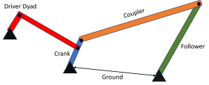
It is important to note that the Grashof criterion only applies to four-bar linkages. For five-bar linkages and higher, there is no single criterion that can be used to determine whether the linkage is capable of continuous rotation. However, it is a common practice to make a non-Grashof mechanism into a Grashof mechanism by adding a short crank link and a connector link to a mechanism to drive it. This is called adding a driver dyad and will be discussed in the mechanism synthesis section next.
Kinematic Inversion
All for the mechanisms that can be made by keeping the link lengths constant but changing which link is held stationary (the ground link) are known as kinematic inversions. Since each link can be held stationary, there are as many inversions as there are links in any given mechanism. Each kinematic inversion of a mechanism will exhibit different motion of the links.
