Mechanism Force, Velocity and Acceleration Analysis
Force Analysis
There are two main objectives when considering how forces act on and through a planar mechanism. First, mechanical advantage is figure of merit for a mechanism that represents the effectiveness of turning input torque or force into output torque or forces. Secondly, static and dynamic force analysis is used to understand how forces act on each link in the mechanisms and are transferred to components such as bearings and pins. Both graphical and computational techniques are commonly used for force analysis.
Mechanical Advantage
In general, mechanical advantage related input and output torques. For a gearing system, this is the gear ratio which is constant as long as the diameter of the gears is constant. However, for a linkage mechanism, the mechanical advantage ratio changes as the mechanism moves. Consider the 4-bar linkage below as an example. Mechanical advantage is determined as the ratio of the driver length times the sine of the integral angle and the length of the follower times the sine of its internal angle. As a formula:
[latex]MA = \frac{L_4*sin{\lambda}}{L_2*sin{\beta}}[/latex]
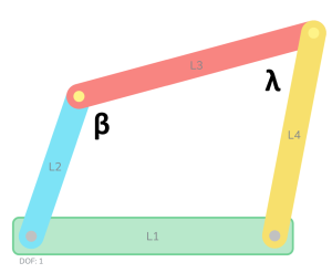
By inspection of this equation, you can see that mechanical advantage changes as the internal angles change (mechanism movement). Further, as the angle [latex]\beta[/latex] goes towards zero, the mechanical advantage increase towards infinity (not possible with real materials but an artifact of mathematic kinematics). An angle of zero occurs when link 2 is in line with the ground link L1. This is the same position as when determining the minimum transmission angle. This is the reason that the minimum transmission angle is a good figure of merit for a mechanism. The ratio can be used to compute the ratio of input and output torque. For example, if a motor provides a known torque at a given rpm, the output or follower torque can also be determined.
Static Force Analysis
Static analysis is used by machine designers for mechanisms analysis in two general cases. First, to determine what is the required force needed to initiate the movement of a mechanisms that is intended to continuously move. Secondly, for some mechanisms the main objective of the mechanisms is to be stationary and apply some output force. Force analysis on the linkage mechanisms is based on the underlying assumption that each link is a rigid body. Force analysis requires a kinetic (relating to energy) instead of a kinematic approach. For position, velocity and acceleration, the linkage is described by link lengths, angles and time. For force analysis, we must include forces and mass. For static analysis, the governing equations for the linkage mechanism as a whole and each link is that the sum of all forces and the sum of moments are equal to zero, this is application of Newton's second law. Further, the forces one link puts on another or equal in magnitude, colinear, and opposite in directions on each other; Newton's third law.
Dynamic Force Analysis
Dynamic force analysis involves determining the centroid and mass moment of inertia of the linkage mechanism. These topics are covered extensively in dynamics textbooks in the area of rigid body kinetics. For simple problems, hand-based computation for single positions are reasonable. However, most machine design contexts, the designer is interested in the forces throughout the full range of mechanism motion. Most modern CAD software has built in motion dynamics analysis both from a kinetic and kinematic.
Velocity and Acceleration Analysis
Velocity and acceleration analysis for planar kinematic linkages is a method to determine the motion characteristics of the links and joints in a mechanism. The reasons to perform this analysis are to evaluate the performance, efficiency, and safety of the mechanism, as well as to design or optimize its parameters. For example, at what input rpm will the motor need to run to move the end of the mechanism a precise speed? Or what is the maximum acceleration of the link or a point on the link as it travels?
Both graphical and analytical solutions can be used for kinematic velocity and acceleration analysis. Graphical techniques are useful for determining velocity and acceleration at critical points, while analytical techniques are useful for solving for the whole range of motion.
Vector Loop Velocity and Acceleration Analysis
Recall that we can represent the position of each link as a vector and each vector can be described equivalently with Euler's number or sines and cosines. The value of using the Euler approach is that it is fairly trivial to take derivative of all the power of e, namely [latex]\frac{d}{du} e^u = e^u[/latex]. Thus, a time derivative (rate of change of the angles) can be used to determine angular velocity of any in the mechanism. As with vector loop solutions for position analysis, the link lengths and at least one angular position must be known to solve for the others positions at any given time. Additionally, for velocity analysis, one angular velocity must be known. In the machine design context, this is often the known motor powering the mechanism or the desired velocity of the mechanism to find a suitable actuator. For acceleration analysis, all of the above constraints hold plus one angular acceleration must be known. However, a very common design mechanism design problem is to evaluate the acceleration of when the actuating motor is at a constant velocity (and thus angular acceleration is zero). In this situation, while the input angular acceleration is constant the other link angular accelerations are not necessarily zero.
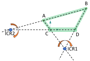
Velocity Centers
The velocity center of a planar linkage mechanism is a point on the mechanism that has zero velocity at a given instant in time. It is also known as the instantaneous center of rotation (ICR). The velocity center can be used to analyze the motion of the mechanism and to design mechanisms for specific applications. ICR is a point at which it appears at that instant a linkage is rotating about. For a four-bar linkage, all of the revolute joints will be ICR. However, the number of instant centers in a linkage mechanism depends on the number of links in the mechanism. A linkage mechanism with links will have instant centers. For a four-bar linkage that means equals 6. So where are the other 2 centers? They can be found graphically by extending lines from the links and finding their intersection points of those lines. These points act like pivots at that point. Machine designers use the path that the instant centers travels through to evaluate the efficiency of the planar mechanism. At an critical points, the velocity centers are also useful for determining the velocity of any point on a linkage. If one velocity is known (for example the linear velocity of point A in the picture below based on known an input angular velocity and link length), then the magnitude of the velocity of point B can be readily determined by measure the distance between the ICR point and the point of interest. By equation, that is:
[latex]V_A = \omega_{ICR1} * Length_{ICR1 to A}[/latex]
and
[latex]V_B=\omega_{ICR1} * Length_{ICR2 to B}[/latex]
Depending on how you prefer to learn material, you can follow along with a printed reading of analytical velocity and acceleration analysis here. Or...
Follow along as Professor Cummins explains how to do velocity and acceleration analysis on several examples.
Velocity Analysis
Velocity Ratios
Acceleration and Velocity Analysis
