Mechanism Posture and Position Analysis
Critical Position Location Analysis
Position analysis, also called posture analysis is for understanding what combination of angular position of the links lead to positions or postures that are of interest to the designer. Position analysis can be accomplished graphically or analytically. Both methods are about as fast. However, it is recommended that designers always sketch out solutions to verify any computational results.
Minimum Transmission Angle
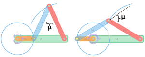
The minimum transmission angle for a planar mechanism is the smallest angle between the input and output links. It is an important measure of the efficiency and performance of a mechanism. A high minimum transmission angle indicates that the mechanism is efficient at transmitting power from the input link to the output link. A low minimum transmission angle can lead to power losses and increased wear and tear on the mechanism. As a general design principle, if the primary objective of the mechanisms is transmitting power or force, than a minimum transmission angle of 45 degrees is best.
For non-Grashof mechanisms, the angle between coupler and follower links can be zero (or 180 degrees). This is an important toggle position that will be discussed below. Thus, the minimum transmission angle is not usually a useful figure of merit for non-Grashof mechanisms. For Grashof mechanism, the minimum transmission angle occurs at one of two postures. The minimum transmission angle can be found when the crank or driver link is at either 0 degree or 180 degrees with respect to ground. Worded another way, when the driver link is colinear with the ground link.
To find the minimum transmission angle, you can utilize graphical techniques such as hand drawing the linkage at a scale or software like MotionGen or CAD. Additionally, you can use the law of cosines if link lengths are known. When links of a 4-bar mechanism are colinear, the resulting shape is a triangle. The law of cosines is usually written as:
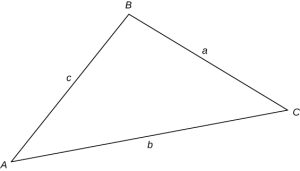
[latex]c^2 = a^2 + b^2 - 2ab*\cos(C)[/latex]
where the a, b, and c are the sides of the triangles and C is internal angle across from side c. For a Grashof mechanisms with the driver link colinear with the ground link, the minimum transmission angle can be found by solving the internal angle. Using the labels in the figure above the two possible solutions are:
[latex]\cos^{-1}(\mu) = \frac{(Ground- Driver)^2 - L_2^2 - L_3^2}{-2L_2L_3}[/latex]
or
[latex]\cos^{-1}(\theta) = \frac{(Ground+ Driver)^2 - L_2^2 - L_3^2}{-2L_2L_3}[/latex]
[latex]\mu = 180 - \theta[/latex]
If the minimum transmission angle is larger than about 45 degrees, then changing the link lengths such as increasing the driver length or decreasing the ground link can improve the efficiency of the power transfer of the mechanism.
Toggle Positions
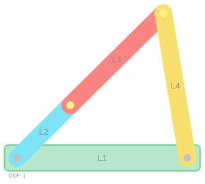
Another special mechanism posture occurs when links are colinear. These positions are called toggle positions. The reason you as machine designer should about toggle positions is that toggle positions are the positions where a mechanism can get stuck and need force to overcome. Additionally, toggle positions can be used to enable a locking type of behavior. For a Grashof mechanism, the toggle position is when the driver and coupler (labeled links 2 and 3 below) are co-linear. If a mechanism is moving slowly it is possible that this posture might result in high amounts of friction. This can be overcome by ensuring that enough force or momentum is provided to the mechanism to pass through this toggle position.
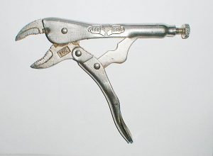
What is often more useful for machine design is toggle positions for non-Grashof mechanisms. The toggle position of coupler and follower (or link 3 and 4 from the image below) can be intentionally designed to provide a locking feature for the mechanism. For example, this is used in linkage mechanisms that support folding table legs and locking pliers. If you have put away a folding table or used a pair of locking pliers you may be familiar with the force needed to knock the mechanism out of the toggle position.
Once again, the law of sines and the law of cosines is useful to determine at what position angle the mechanism will be in a toggle position. Additionally, you can use hand or software tools to draw the mechanisms at toggle position and then measure the angles. These will be very useful when determining how to control and drive the mechanism.
Link Position and Displacement
Position or displacement analysis for planar mechanisms is the process of determining the position of every link and joint of a mechanism relative to a fixed reference frame. This is an important step in the design and analysis of machines, as it allows the calculation of velocities, accelerations, forces, torques, and other dynamic parameters. Position or displacement analysis can be performed using various methods, such as graphical, analytical, or numerical techniques. Graphical methods involve drawing the mechanism and its links to scale and measuring the position of each point of interest. Analytical methods involve deriving equations that relate the position of each link and joint to the input variables, such as angles or lengths. Numerical methods involve using iterative algorithms or computer software to solve the equations obtained from analytical methods.
Drawing mechanisms by hand to solve for positions is a useful tool for early analysis and enables a designer to see the mechanism shape and anticipate potential trouble areas. Usually, the mechanism is drawn at the extreme positions of interest. However, if the designer wants to explore multiple positions or determine displacement, graphical methods using CAD or other drawing tools will provide more versatility and more accurate measurements. CAD based approaches are also straight forward. Given the link lengths and ground locations, the mechanisms can be virtually manipulated into the desired position and displacements can be measured by the software from those positions.
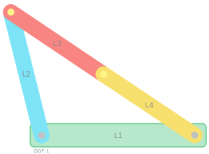
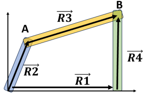
Analytical or computational position analysis is also common. In the figure below you can see that we can represent a mechanisms as a vector loop diagram. That is, if each link was represented as a vector, than we could move from point 0 to point B two equivalent ways. These are:
[latex]\vec{R2} + \vec{R3} = \vec{R1} + \vec{R4}[/latex]
This is reorganized for future solving as:
[latex]0 = \vec{R2} + \vec{R3} - \vec{R4} - \vec{R1}[/latex]
The power of this vector representation is that it can support position, velocity, and acceleration analysis as a system of equations. Euler's formula allows us to represent any of those linkage vectors as:
[latex]\vec{R2} = R2*e^{j*\theta_2} = R2* (\cos{\theta_2} + j*\sin{\theta_2})[/latex]

Where R2 the length of link 2. The term j represents the imaginary component in mathematics which was actually a dismissive term supposedly made by René Descartes. Carl Friedrich Gauss described them as "lateral" which is more useful for our understanding. In this context, the lateral just represent the component in the direction orthogonal to the ground (usually a local y direction).
Using this approach, an analytical solution can always be found for a mechanism by solving the system of equations for the vector loop by grouping the solutions into the local horizontal (x) and vertical (y) directions. If angle measurements for the links are made with respect to the ground link which defines the local x direction, and recalling that cos(0) is 1 and sin(0) is 0, then the two sets of equations can be written below:
In the x direction:
[latex]0 = R2*\cos{\theta_2} + R3*\cos{\theta_3} - R4*\cos{\theta_4} -R1*1[/latex]
and in the y direction:
[latex]0 = R2*\sin{\theta_2} + R3*\sin{\theta_3} - R4*\sin{\theta_4} [/latex]
With known link lengths (after synthesis, these should be known) and one known angle (such as the driver position angle), the other two angles can be solved and position of the links determined.
Specific solutions for common mechanism are available such as crank-slider mechanisms commonly known as piston equations and there are many general linkage calculator tools available.
As well as the MotionGen software linked above, there are a variety of calculators available to support machine and mechanisms designer.
Softintegration has a variety of web-based tools for solving for synthesis, displacement, and velocity analysis.
Four-Bar Linkage Analysis and Synthesis
The community file exchange for Matlab has many user-built tools for solving 4-bar and similar mechanisms. Additionally, the toolbox called Simscape is very useful for detail modeling when designers know properties of the linkage such as mass and shape and want detailed calculations and simulations.
