Linkages and Mechanisms
Watch and Follow Along with Dr. Slocum – FUNdaMENTALS of Design – Links
Watch Dr. Slocum’s Video below. You can follow along with the slides and images here.
A Wide World of Mechanisms
Ready to be blown away by what is possible out there?
Explore Dr. Nguyen Duc Thang Youtube channel to see all the 1000’s of mechanisms he has generated and animated.
https://www.youtube.com/@thang010146/videos
Links, Joints, and Terminology of Linkages
The study of the mathematics of machines, sometimes called theory of machines, focusses on how to generate linkages to achieve a desired conversion of power to achieve a desired function. As with any field if study there are specific terms we will need to cover.
|
Kinematic chain |
A kinematic chain is a group of links connected by joints. A kinematic chain can be open or closed. An open kinematic chain has at least one free link, meaning that it is not connected to any other links. A closed kinematic chain has no free links. |
|
Mechanism |
A mechanism is a kinematic chain with at least one fixed link. A kinematic chain is a group of links connected by joints. A link is a rigid body that can move relative to other links. A node is a point where two or more links are connected. |
|
Links |
Links are the rigid bodies that make up a kinematic chain. Links can be any shape or size, but they must be rigid enough to withstand the forces that are applied to them. |
|
Nodes |
Nodes are the points where two or more links are connected. Nodes can be simple, such as a pin joint, or they can be complex, such as a cam and follower joint. |
|
Binary links |
Binary links are links that are connected to two other links. Most links in a kinematic chain are binary links. A link with two nodes is the least number a link can have and still be considered a link. |
|
Trinary links |
Trinary links are links that are connected to three other links. Trinary links are less common than binary links, but they can be used to create more complex mechanisms. There are other named links (for example quaternary links) based on the number of nodes as well. |
|
Joints |
Joints are the connections between links. Joints allow links to move relative to each other. There are many different types of joints, each of which allows a different type of motion. |
|
Degrees of freedom |
The degrees of freedom of a mechanism are the number of independent motions that the mechanism can make. The degrees of freedom of a mechanism are determined by the number of joints and the type of joints in the mechanism. |
|
Planar Mechanism |
A planar mechanism is a system of linkages whose motion is constrained to a two-dimensional plane. This means that all of the relative motions of the parts are in the same plane or in parallel planes.
|


Common Types of Mechanisms
Cornell University has an incredible collection of mechanisms that you should plan to visit in person someday but ALSO has freely available images and animations to view: Reuleaux Kinematic Mechanisms Collection | Cornell University Library Digital Collections.
General Model Classes (Voigt Taxonomy)
| From the Cornell University Kinematics Models for Design Digital Library
K. Complex Slider Crank Mechanisms |
N. Ratchet Mechanisms
U. Rotating Arm Guide Mechanisms |
Special Linkage Mechanisms
There are a fee common linkage mechanisms used in many different kinds of mechanical products and systems to achieve the desired functions.
Common Linkage Mechanism in Machines |
| Ratchet and Escapement
A ratchet mechanism is a device that allows continuous motion in one direction, while preventing motion in the opposite direction. It consists of two main parts: a ratchet wheel (or gear) with teeth on one side, and a pawl that engages with the teeth. The pawl is spring-loaded, so it presses against the teeth of the ratchet wheel and prevents it from moving backward. When force is applied to the ratchet wheel in the forward direction, the pawl slides over the teeth and allows the wheel to rotate. However, when force is applied in the backward direction, the pawl catches against the teeth and prevents the wheel from rotating. An escapement mechanism is a device that controls the release of energy in a mechanical system, such as a clock or watch. It works by allowing the system’s timekeeping element (usually a pendulum or balance wheel) to oscillate back and forth, while transferring energy from the system’s power source (usually a spring or weight) to the timekeeping element at a regular pace. This keeps the timekeeping element oscillating at a constant frequency, which allows the system to keep accurate time.
|
| Indexing
An indexing mechanism (like the Geneva mechanism shown) is a device that allows a shaft or other rotating element to be positioned in precise increments. It works by using a series of evenly spaced teeth or slots to engage with a follower pin or other indexing element. As the rotating element turns, the follower pin engages with the teeth or slots and indexes the element forward one step at a time.
|
| Swinging or Rocking
A swinging or rocking 4-bar mechanism is a type of linkage that converts rotary motion into oscillating motion. It consists of four links connected together by four joints, with one of the links fixed to a frame. The other three links are free to move, and the link that oscillates is called the rocker. When the input link is rotated, it drives the other links to move, causing the rocker to swing or rock. The angle of the rocker is determined by the lengths of the links and the input angle. In windshield wipers, the swinging or rocking 4-bar mechanism is used to convert the rotary motion of a motor into the back-and-forth motion of the wiper blades.
|
| Reciprocating
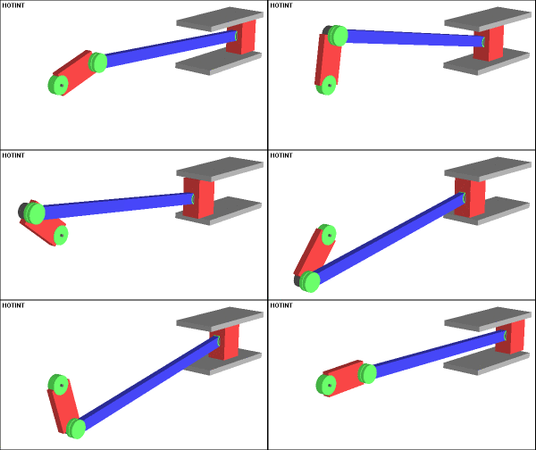
A reciprocating mechanism is a device that converts rotary motion into linear motion. It consists of a rotating element (such as a crank or cam) and a sliding element (such as a piston or plunger). The rotating element drives the sliding element back and forth, creating reciprocating motion. Quick-return is a design feature of some reciprocating mechanisms that allows the return stroke (the stroke in which the sliding element moves back to its starting position) to be completed faster than the working stroke (the stroke in which the sliding element performs its useful work). This is achieved by designing the mechanism so that the sliding element travels a shorter distance and/or at a higher speed during the return stroke. The advance-to-return ratio is a measure of how much faster the working stroke is than the return stroke. It is calculated by dividing the distance traveled during the working stroke by the distance traveled during the return stroke. A ratio greater than 1 indicates a quick-return mechanism.
|
| Curve Generator
A curve generating mechanism is a device that converts rotary motion into a curved path. It consists of a number of interconnected links that move the end of one link in a curved path as the input link is rotated. Curved path guiding is often needed in manufacturing machines to guide product through operations at a constant rate.
|
| Straight-Line Generator
A straight line generating mechanism is a device that converts rotary motion into linear motion with very little deviation from a straight line. It does this by using a system of linkages to constrain the motion of a point to a straight line. One common type of straight line generating mechanism is the Peaucellier-Lipkin inversor. This mechanism consists of four links connected together by four joints. The input link is rotated by a motor, and the other three links are constrained to move in a straight line. The point at which the three links intersect traces out a straight line as the input link is rotated. Another common type of straight line generating mechanism is the Watt’s linkage. This mechanism is similar to the Peaucellier-Lipkin inversor, but it is simpler to design and manufacture. However, it does not produce as accurate of a straight line as the Peaucellier-Lipkin inversor.
|

