Introduction to Geometric Dimensions and Tolerances
GD&T Definitions and Basics
Geometric Dimensioning and Tolerancing (GD&T) is a system for defining and communicating engineering tolerances via a symbolic language on engineering drawings and computer-generated 3D models that describes a physical object’s nominal geometry and the permissible variation thereof. GD&T is used to communicate the design intent of a part, focusing on the function of the part rather than its exact dimensions. GD&T allows the designer to specify larger tolerances for less important features, resulting in a part that is easier and cheaper to produce. GD&T is based on communication using standard symbols to define features and their allowable tolerances. There are several standards that describe the symbols and rules of GD&T, such as the American Society of Mechanical Engineers (ASME) Y14.5 Standard and the International Organization for Standardization (ISO) Geometrical Product Specifications (GPS). These standards provide a common language for engineers and manufacturers to ensure that the parts meet the functional requirements of the design.
GD&T Symbols
Go through the various symbols described here:
GD&T Symbols | GD&T Basics (gdandtbasics.com)
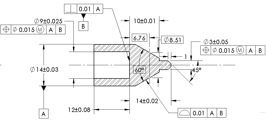
Any use that to determine what everything on the following part drawings means:
5 Steps to creating GD&T Drawings for Superior Quality (solidworks.com)
General Concepts for GD&T
A feature is any physical portion of a part, such as a surface, hole, slot, pin, etc. A feature can be either a feature of size or a non-size feature. A feature of size is one where the variation in its size affects the function or assembly of the part, such as a shaft diameter or a hole spacing. A non-size feature is one where the variation in its form, orientation or location affects the function or assembly of the part, such as a surface flatness or a hole perpendicularity.
A feature control frame is a rectangular box that contains the geometric characteristic symbol, the tolerance value, the datum references (if any), and any modifying symbols or modifiers. The feature control frame is attached to the dimension of the feature that it applies to by a leader line. The feature control frame specifies the tolerance zone for the feature and how it is related to other features or datums.
A basic dimension is a numerical value that defines the exact size, profile, orientation or location of a feature. It is usually shown in a rectangular box and does not have any tolerance associated with it. The tolerance for a basic dimension is specified by the feature control frame that references it. Basic dimensions are used to define the true profile or the true position of a feature.
A datum feature symbol is a label that identifies a physical feature of a part that acts as a datum. A datum is an imaginary plane, axis or point that serves as a reference for other features. A datum feature symbol consists of a letter enclosed in a square frame, which is attached to the outline of the feature by a leader line. The letter indicates the order of precedence of the datum in relation to other datums.
A feature of size is one cylindrical or spherical feature, or two opposed elements or opposed parallel surfaces, associated with a size dimension. A feature of size has an axis (for cylinders or spheres) or a center plane (for opposed elements or surfaces) that can be used to establish a datum.
Full indicator movement (FIM) is the total movement of an indicator’s measuring tip or contact point as it passes over an entire surface. FIM is used to measure surface variations such as flatness, straightness, circularity or cylindricity.
Least material boundary (LMB) is an imaginary boundary around a feature of size that represents the smallest size allowed by the tolerance. LMB is used when applying maximum material condition (MMC) modifier to an internal feature of size, such as a hole.
Least material condition (LMC) is the condition where an external feature of size (such as a shaft) contains the least amount of material within its tolerance zone, or where an internal feature of size (such as a hole) contains the most amount of material within its tolerance zone. LMC is used to specify assembly clearance between mating parts.
Maximum material boundary (MMB) is an imaginary boundary around a feature of size that represents the largest size allowed by the tolerance. MMB is used when applying maximum material condition (MMC) modifier to an external feature of size, such as a shaft.
Maximum material condition (MMC) is the condition where an external feature of size (such as a shaft) contains the most amount of material within its tolerance zone, or where an internal feature of size (such as a hole) contains the least amount of material within its tolerance zone. MMC is used to specify assembly interference between mating parts.
Projected tolerance zone is an imaginary cylinder or cone that extends beyond the surface of a hole or stud to control the position of another part that will be inserted into or over it. Projected tolerance zone is used when there is a functional requirement for alignment between mating parts beyond their mating surfaces.
Regardless of feature size (RFS) is a default condition that applies when no material condition modifier (such as MMC or LMC) is specified for a feature control frame. RFS means that the tolerance zone for the feature remains constant regardless of its actual size within its size tolerance.
Virtual condition is an imaginary boundary around a feature of size that represents the worst-case scenario for assembly with another part. Virtual condition is equal to MMB for external features and LMB for internal features when MMC modifier is applied, and equal to LMB for external features and MMB for internal features when LMC modifier is applied.
Types of Tolerances
Form Tolerances:
Flatness: A form tolerance that controls the deviation of a surface from a perfect plane. It can be applied to any surface, regardless of its size or shape.
Straightness: A form tolerance that controls the deviation of a line element or an axis from a perfect straight line. It can be applied to a feature of size (such as a cylinder) or to a non-size feature (such as a slot).
Circularity: A form tolerance that controls the deviation of a circular feature from a perfect circle. It can only be applied to circular features of size, such as holes or pins.
Cylindricity: A form tolerance that controls the deviation of a cylindrical feature from a perfect cylinder. It can only be applied to cylindrical features of size, such as shafts or bores.
Orientation Tolerance:
Parallelism: An orientation tolerance that controls the parallelism between two features or between a feature and a datum plane. It can be applied to any feature of size or non-size feature that has two parallel surfaces or elements, such as plates, blocks, slots, etc.
Perpendicularity: An orientation tolerance that controls the perpendicularity between two features or between a feature and a datum plane. It can be applied to any feature of size or non-size feature that has two perpendicular surfaces or elements, such as holes, pins, slots, etc.
Angularity: An orientation tolerance that controls the angular deviation between two features or between a feature and a datum plane. It can be applied to any feature of size or non-size feature that has two angular surfaces or elements, such as wedges, cones, slots, etc.
Runout Tolerances:
Runout: A composite tolerance that controls the variation in surface elements of a rotating part in relation to a datum axis during one full rotation. It is composed of two types: circular runout and total runout.
Circular Runout: A runout tolerance that controls the variation in circularity and coaxiality of a surface element at any given cross section of a rotating part in relation to a datum axis. It can be applied to any circular or cylindrical feature of size, such as rims, gears, shafts, etc.
Total Runout: A runout tolerance that controls the variation in circularity, coaxiality, straightness, taper, and profile of an entire surface of a rotating part in relation to a datum axis. It can be applied to any circular or cylindrical feature of size, such as drums, rollers, shafts, etc.
Profile Tolerance:
Profile of a Line: A profile tolerance that controls the variation in shape and location of an individual line element on a surface in relation to its true profile. It can be applied to any line element on any surface, regardless of its size or shape, such as curves, contours, edges, etc.
Profile of a Surface: A profile tolerance that controls the variation in shape and location of an entire surface in relation to its true profile. It can be applied to any surface, regardless of its size or shape, such as planes, spheres, cones, etc.
Location Controls:
Concentricity: A location control that controls the coaxiality between two features or between a feature and a datum axis. It can be applied to any circular or cylindrical feature of size, such as holes, pins, shafts, etc.
Symmetry: A location control that controls the symmetry between two features or between a feature and a datum plane. It can be applied to any feature of size or non-size feature that has two symmetrical surfaces or elements, such as plates, blocks, slots, etc.
Position Tolerance: A location control that controls the variation in location of a feature or a group of features in relation to one or more datum features. It can be applied to any feature of size or non-size feature that has a defined position, such as holes, pins, slots, etc.
Follow along with the lecture below to understand how to put these concepts together.
