Fits and Tolerances
One of the most significant parameters controlling the choice of manufacturing methods is the desired tolerance or the produced part. That is, to what exactness and allowed variance can part dimensions fluctuate such that they still perform their over-all function and can be properly assembled with other parts. Different manufacturing processes can produce parts with an expected amount of variation in their dimensions. Therefore, one of the first steps in design for manufacturing is determining the appropriate level of tolerance and correctly specifying that on part drawings and other related documentation. This section details tolerance selection in general and how to specify a desired tolerance.
Tolerancing
Tolerancing is the process of specifying the acceptable range of variation in the dimensions of a part. Tolerancing is essential for mass production, where assemblies must fit together with the goal of 100% interchangeability of parts. However, no part can be made exactly to the nominal size, which is the ideal or target dimension. Therefore, tolerancing allows for some deviation from the nominal size without compromising the functionality or quality of the product.
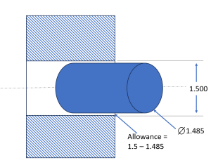
There are several terms and concepts related to tolerancing that a mechanical product designer should know. The basic size is the theoretical size used as a starting point for applying tolerances. The limits are the maximum and minimum permissible dimensions of a part. The allowance is the intentional difference between the maximum material condition (MMC) and the least material condition (LMC) of mating parts. The MMC is the condition where a part has the maximum amount of material within the specified limits. The LMC is the opposite condition, where a part has the minimum amount of material within the specified limits. These will be discussed further in the chapter on geometric dimensioning and tolerancing.
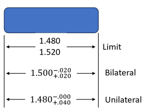
Tolerances are implemented through the manufacturing process and are specified on part drawings. There are different methods of reporting tolerance on a drawing or a model. One method is limit dimensioning, where the upper and lower limits are given directly. Another method is unilateral tolerance, where only one limit is given and the other limit is implied by adding or subtracting a tolerance value from the basic size. A third method is bilateral tolerance, where both limits are given by adding and subtracting a tolerance value from the basic size.
Tolerances should be chosen very carefully by considering the requirements and constraints of the design problem. Tolerances must ensure that parts meet the desired quality standards and perform as intended. However, higher tolerances can also increase the cost of production exponentially, as they require more precise machines, tools, and inspection methods. Therefore, a good product designer should balance between quality and cost when selecting tolerances for parts. Note that default CAD modeling dimensions are often given in tighter tolerances than necessary and choosing these tolerances for no other reason can significantly increase the cost of production.
Selecting a Tolerance for Your Part
- Consider the function and purpose of the part. What are the critical dimensions that affect its performance? How does it fit with other parts in the system? What are the environmental conditions that may affect its dimensions, such as temperature, humidity, or wear?
- Use standard tolerances whenever possible. Standard tolerances are widely used and accepted in the industry and are based on empirical data and experience. They can simplify the design and manufacturing process and reduce errors and confusion. Standard tolerances can be found in various reference books, such as ANSI/ASME standards, ISO standards, or GD&T (Geometric Dimensioning and Tolerancing) standards.
- Use statistical methods to analyze the variation and distribution of dimensions. Statistical methods, such as Six Sigma, can help determine the optimal tolerance that minimizes defects and maximizes quality. Statistical methods can also help estimate the cost and benefit of different tolerance levels and compare them with customer requirements and expectations.
- Perform tolerance analysis and simulation to verify the design. Tolerance analysis is a method of calculating the cumulative effect of tolerances on a dimension or a feature. Tolerance analysis can help identify potential problems or conflicts in the design and evaluate the feasibility and robustness of the tolerance scheme. Tolerance simulation is a method of testing the design using computer models or physical prototypes that incorporate random variations in dimensions. Tolerance simulation can help validate the performance and functionality of the design under different scenarios and conditions.
Fits
A fit system is a way of specifying how much clearance or interference there is between two parts that are supposed to fit together. One of the most common fit systems is the hole/shaft system, which is based on an ANSI or ISO standard. This system applies to cylindrical parts that have a hole and a shaft that go into the hole.
There are three types of fits in the hole shaft system: clearance fits, interference fits, and transition fits. A clearance fit means that there is always some space between the hole and the shaft, even when they are pushed together as much as possible. That means when a shaft is produced at the largest of its allowed tolerance and the hole is made to the smallest of its allowed tolerance, there is still clearance between the parts. A clearance fit allows for easy assembly and disassembly, but it may result in some looseness or play between the parts. An interference fit means that there is always some overlap between the hole and the shaft, even when they are pulled apart as much as possible. An interference fit requires force or heat to assemble and disassemble, but it provides a tight and rigid connection between the parts. A transition fit means that there may be either clearance or interference between the hole and the shaft, depending on the actual sizes of the parts. A transition fit can provide a moderate amount of tightness or looseness, depending on the application.
The ANSI and ISO standards (ANSI/ASME B4.1 and B4.2 and ISO 286-1 and 286-2) defines different classes of fits for each type of fit, based on how much tolerance is allowed for the hole and the shaft dimensions. The classes of fits are named using letters and numbers, such as RC, LC, LT, LN, and FN. The letters indicate the type of fit (R for running or sliding, L for location or alignment, F for force or shrink), and the numbers indicate the degree of tolerance (1 for very loose, 9 for very tight). For example, an RC1 fit is a very loose clearance fit, while an FN9 fit is a very tight interference fit.
The standard also uses capital letters for holes and lowercase letters for shafts. For example, a hole with an H7 tolerance means that its actual size can vary from 0 to +0.025 mm from its nominal size, while a shaft with an h6 tolerance means that its actual size can vary from 0 to -0.01 mm from its nominal size. If we want to have a transition fit between these two parts, we can use an H7/h6 fit designation. This means that the hole can have a diameter from 10 to 10.025 mm, while the shaft can have a diameter from 9.99 to 10 mm.
Using the Machinery’s Handbook or online calculators (like this or this one) can help you determine the sizing and tolerancing for a desired fit.
When choosing a fit system for a design, we need to consider what we have more control over: the hole or the shaft. If we are using a standard component that has a fixed size, such as a bearing or a motor, we need to match our hole or shaft to that component. For example, if we have a bearing with an H7 tolerance, we need to make our shaft with an h6 or smaller tolerance to ensure a transition fit. If we have control over both the hole and the shaft dimensions, we may find it easier to make the shaft more precise than the hole, since it is usually easier to machine tighter tolerances on the shaft than a circular hole.
Another factor that affects our choice of fit system is the international tolerance grade (ITG) that defines how accurate our manufacturing process can be. The ITG ranges from IT01 (very high precision) to IT16 (very low precision), and it determines how much variation we can expect from our nominal dimensions. The ITG depends on the type of manufacturing method we use, such as turning, milling, drilling, etc. The higher the ITG, the larger the tolerance zone we need to allow for our parts. The ITG also helps us select the appropriate class of fit from the ANSI standard.
The hole shaft system is not limited to cylindrical parts only. We can also use it for other types of mating parts that require sliding or alignment, such as linear slides or guides. We just need to apply the same principles of clearance, interference, and transition fits to these parts as well.
The best way to understand fit systems is to physically try some fits yourself with parts and have a “feel” for the different types of fits. Second best, watch the video below to see the types of interference and best practices for specifying fit systems.
